



Rubber Spiral Radiator Hose Production Line Supplier
This production line is specifically designed for manufacturing rubber hoses with a spiral-wound structural reinforcement layer. Its core utilizes a spiral winding machine to wind reinforcing filaments onto the hose at specific angles, forming a high-strength support skeleton. The line integrates complete processes, including rubber extrusion, cooling, winding, secondary cover application, and automatic winding (optional robotic system). With a high degree of automation, the produced hoses exhibit excellent pulse fatigue resistance and compressive strength, providing a reliable solution for applications such as automotive brake lines, fuel lines, and hydraulic hoses.
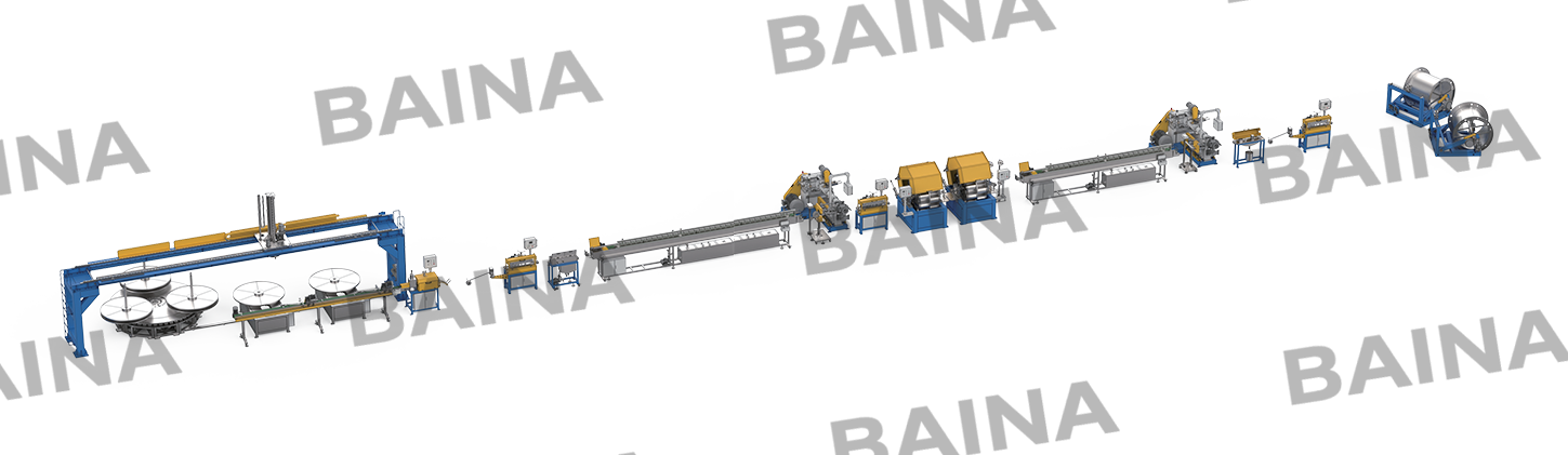
Rubber Spiral Radiator Hose Production Lines: Equipment, Process, and Quality Factors
What Defines a Rubber Spiral Radiator Hose Production Line
A rubber spiral radiator hose is not a straight extrusion. It is a reinforced, curved hose designed to handle hot coolant under pressure while fitting into tight engine compartments. The spiral refers to the textile or wire reinforcement wound at a precise angle around the rubber tube before the cover goes on. The rubber spiral radiator hose production line that makes this hose differs significantly from a general-purpose rubber hose line.
Equipment Components and Their Functions
Rubber Hose Extrusion Machine for the inner tube
The first extruder must produce a tube with a consistent wall thickness and a smooth internal bore. Any surface imperfection inside the hose creates a turbulence point. Coolant flow slows. Erosion accelerates. The Rubber Hose Extrusion Machine uses a pin barrel design for EPDM rubber, which is sticky and requires aggressive screw geometry. A cold-feed configuration works best here because EPDM remains stable at room temperature.
The extrusion die includes a mandrel that forms the hollow center.
Laser measurement after the extruder checks the wall thickness every few milliseconds.
Feedback loops adjust screw speed and haul-off rate automatically when thickness drifts.
Spiral winding heads
Unlike braiders, where carriers cross over each other, spiral winders wrap reinforcement around the tube in parallel layers. One head lays reinforcement at a +54° angle. A second head downstream lies the next layer at -54°. This opposing angle pattern balances internal pressure forces.
Each winding head contains bobbins mounted on rotating rings. The tube passes through the center as the ring spins. Tension control on each bobbin matters critically. Uneven tension creates gaps in the spiral layer. Those gaps become weak points after curing.
Second Rubber Hose Extrusion Machine for the cover
The cover extruder applies the outer layer over the reinforced tube. This extruder uses a crosshead die that surrounds the incoming reinforced tube without disturbing the spiral winding. The cover compound contains UV stabilizers and ozone protectants because radiator hoses live under the hood where heat and electrical sparking produce ozone.
The cover thickness typically runs 1.5–2.5mm. Too thin, and the reinforcement shows through or abrades against engine components. Too thick, and the hose becomes stiff and hard to route through tight bends. The second Rubber Hose Extrusion Machine maintains this thickness within ±0.2mm across the entire production run.
Curing and shaping section
Most radiator hoses are not cured straight. A straight hose would need custom bending after installation, which rarely works. Instead, the production line cuts the reinforced uncured hose to length, places it into a curved mold, and then cures it in a press or autoclave. The mold imparts the exact bend radius and angle needed for a specific engine model.
- Steam autoclaves cure multiple hoses at once in their molds.
Injection molding machines can cure and add fitting ends in the same cycle.
- Some lines use salt bath curing for faster cycles on straight sections before bending.
Production Workflow from Compound to Finished Hose
Step one: inner tube extrusion
Compound strips feed into the first Rubber Hose Extrusion Machine. The screw pushes material through the tube die. A sizing die or vacuum calibration chamber ensures the internal diameter matches specifications. Water cooling sets the tube shape before it enters the winding section.
Step two: spiral reinforcement application
The tube passes through the first spiral winder at a controlled speed. The winder speed must match the extrusion speed exactly. If the winder runs faster, it stretches the inner tube. If slower, the reinforcement wraps loosely and shifts during curing.
Multiple layers go on sequentially. Each layer alternates the winding angle. Some heavy-duty spiral radiator hose production lines apply four or six alternating layers.
Step three: cover extrusion
The reinforced tube enters the crosshead of the cover extruder. The rubber compound flows around the reinforcement, bonding to the outer surface of the inner layer through the openings in the spiral wrap. A vacuum port removes trapped air between the cover and the reinforcement. Air pockets become blisters during curing.
Step four: cutting and molding
The continuous hose passes a flying cutter that cuts to length. Operators place each length into a metal mold shaped for a specific vehicle application—Ford F-Series, Ram truck, Honda Civic, etc. The mold closes, and the assembly moves into a curing press.
Step five: vulcanization
Mold temperature reaches 150–170°C. Curing time ranges from 15 to 40 minutes depending on wall thickness. The sulfur crosslinks the rubber. The spiral reinforcement bonds into the rubber matrix. When the press opens, the hose holds the curved shape permanently.
Step six: finishing and testing
A trim station removes flash from the mold parting line. The hose undergoes a pressure test—often 2x the working pressure for 30 seconds. A spark test checks for liner irregularities. Only hoses that pass move to packaging.
Common Problems and Quality Indicators
Reinforcement shift during winding
The spiral winder tension drifts. The reinforcement moves off-center. The finished hose has exposed wire or yarn on one side. Detection method: X-ray inspection of uncured hose catches this before curing. Fix: daily tension calibration on each bobbin position.
Comparison with Standard Rubber Radiator Hose Production
Standard radiator hose uses knitted reinforcement, not spiral. The difference shows up in burst pressure and flexibility.
|
Feature |
Spiral radiator hose |
Standard knitted radiator hose |
|
Reinforcement pattern |
Helical alternating angles |
Interlocking knit loops |
|
Burst pressure rating |
8–12 bar |
5–7 bar |
|
Kink resistance under vacuum |
High (spiral structure resists collapse) |
Moderate |
|
Production line complexity |
Requires spiral winders |
Requires braiders (simpler) |
|
Tooling cost for curved shapes |
Higher (more complex mold design) |
Lower |
|
Typical applications |
Heavy-duty trucks, performance cars |
Passenger cars, light trucks |
The spiral radiator hose production line costs more to set up. The winding heads and tension control systems add complexity. But the finished hose handles higher pressure and resists vacuum collapse better. For commercial trucks, diesel pickups, and turbocharged engines, spiral construction is the standard, not the exception.
-

-
No. 18, Chunhui Est. Rd., Yong’An Ind. Area, Xianju, Taizhou, Zhejiang, ChinaRoom 707, Building 1, Baolong Plaza, Hangzhou Sci-Tech City, Yuhang District, Hangzhou, Zhejiang, China+86-576-87685299
+86-571-89059793+86-576-87685311 - Home Machinery&Solutions About Baina Industry Applications Support Info Contact Us
-
Copyright © 2025 by Zhejiang Baina Rubber & Plastic Equipment Co., Ltd. All Rights Reserved.

Rubber Hose Extrusion Machine Manufacturer