1. Product name, specification model and equipment weight size:
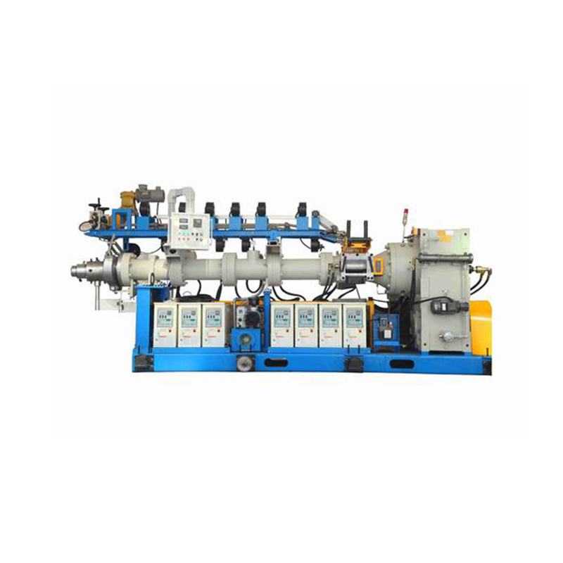
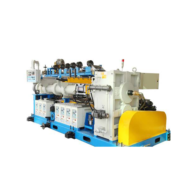
1.1 Product Name: Cold Feed Extruder
1.2 Specification model: XJWP-120X20D
1.3 Equipment weight: about 5 tons
1.4 Dimensions (length X width X height): about 4200X1200X1600mm
1.5 Equipment layout:
1. Special rubber head; 2. Fuselage; 3. Five-section automatic temperature control system; 4. Feed roller device; 5. Feed hopper; 6. AC motor; 9. AC speed control cabinet; 10. Screw cooling Device; 11. Base.
2. Main technical performance parameters:
2.1 Screw diameter: Ф120nn
2.2 Working length of screw: 1920mm
2.3 Screw length to diameter ratio: 20:1
2.4 Screw speed: 4.5-45r/min
2.5 Drive motor power: 110kw-1500r/min
2.6 Power conditions: 3-phase, 380V
2.7 Adapted Mooney viscosity: ML (1+4) 100℃ 50-90
2.8 Design output: 500-600KG per hour
3. Technical description
3.1 Extruder:
3.1.1 Screw: (customized outsourcing)
A. Material: 38CrMoALA;
B. The surface is nitrided;
C. Hardness ≥ HRC62
D. Nitrogen layer depth ≥0.55mm
E. Structure: Adopts German Telest structure, with good extrusion stability and large glue output.
a. It has a hollow structure over the entire length of the screw to facilitate temperature control.
b. The rotation direction of the thread of the rotary joint is opposite to that of the screw.
c. The screw head size is according to the enterprise standard.
d. Water pressure of 10 kg/cm2 inside the screw is tested for more than 1 hour to prevent leakage.
3.1.2 Barrel and bushing:
A. Barrel
a. Welded structure, tempered after welding, Water pressure of 10 kg/cm2 inside the screw is tested for more than 1 hour, no leakage.
b. The fuselage flange connected to the machine head can be processed according to customer requirements.
B. Bush: with exhaust port, the exhaust port does not run rubber
a. Material: 38CrMoALA;
b. The surface is nitridized, and our factory heat treatment workshop has imported nitriding furnace;
c. Hardness ≥ HRC66;
d. Nitrogen layer depth ≥0.55mm;
3.1.3 Feeding roller: structure obtained national patent
A. Material: 38CrMoALA, roller surface nitriding treatment, hardness ≥HRC62, hard layer depth ≥0.55mm;
B. Structure:
a. Internal circulation of water;
b. Can be connected to rotary joint;
c. The feed roller gear is made of 20CrMoTi, and the surface is carburized. The average depth of carburizing is 1.5mm;
d. The feed roller is driven by the gear reducer shaft through the gear, and the speed ratio gear has sufficient strength and wear resistance;
e. The speed ratio gear is lubricated with grease;
f. There is a rubber scraper to scrape off the rubber material on the surface of the roller. The scraper is fixed on the barrel and the gap between the roller and the roller can be adjusted. The feeding roller can be rotated and opened;
g. The feed roller bearing is lubricated with grease.
3.1.4 Reducer
3.1.4.1 Design conditions
A. Working condition coefficient ≥ 1.75
3.1.4.2 Three-stage transmission, parallel shaft output, noise less than 85db(A);
3.1.4.3 The output shaft has a hollow structure, the screw is inserted into it and transmits torque;
3.1.4.4 with peep window;
3.1.4.5 has an oil mark with scale and oil outlet with plug;
3.1.4.6 A lubrication system composed of independent lubricating oil pumps, etc., to facilitate forced lubrication of gears and bearings;
3.1.4.7 There is an exhaust valve on the top of the gearbox, and the oil outlet of the gearbox is located at the bottom of the box;
3.1.5 Temperature control pipeline:
3.1.5.1 The pipeline is arranged on the operation side of the extruder row;
3.1.5.2 The soft connecting pipe should be resistant to temperatures above 120℃;
3.1.5.3 All valves have nameplates;
3.1.5.4 Hydrostatic test, under 10kg/cm2, under 1 hour of hydrostatic test, there is no leakage;
3.1.6 Base:
A. The extruder and the motor are installed on the same base;
B. Pins should be positioned between the upper and lower case of the gearbox;
C. The base has sufficient strength and rigidity to withstand the torque and vibration loads of the extruder;
D. Roughly machining the surface of the base for installation and attachment;
E. There are more than two planes on the base to facilitate installation and alignment;
F. After the standard is installed, the center mark will be printed on the extruder, gearbox and machine base;
G. There are lifting hooks or lifting holes for lifting;
H. The area of the base is as small as possible, but sufficiently removed from the position of the motor mount;
3.1.7 Temperature control device
3.1.7.1 Structure and working principle:
The system adopts forced circulation of media, and controls the temperature of each section independently in six units. Each unit is composed of a water pump, an electric heater, a temperature control instrument, a cooling water on-off solenoid valve, an automatic exhaust valve, a platinum thermal resistance, and an electrical contact pressure. Table (shockproof) and other components, the circulating water pump injects the medium (softened water) into the electric heater (the automatic exhaust valve discharges the gas in the system), flowsthrough the barrel, pipeline, the machine head, and the screw return to the suction port of the pump. After the temperature of each section has been set, the circulating water will heat the barrel, head, screws, etc., by means of a heater, or by the heat produced in the processing of the rubber material, in the working state. Heat is discharged through circulating water, heating power per unit: 6KW, control temperature range: room temperature is 90℃; control temperature accuracy: ± 2℃; (using imported constant temperature machine)
3.1.7.2 Unit description
Unit1: control the screw temperature;
Unit2: control the temperature of the extrusion section of the barrel;
Unit3: controlling the temperature of barrel plasticizing section I;
Unit 4: Control the temperature of barrel plasticizing section II;
Unit 5: Control the temperature of barrel plasticizing section III;
Unit 6: Control the temperature of the feeding section of the barrel;
Unit 7: Control the head temperature.
3.1.7.3 Suppliers and models of main supporting parts
Circulating water pump: German Wilo Company
Temperature regulator: Omron
3.1.8 Electrical control system:
The extruder is controlled by a DC drive and has protection functions such as overcurrent, overload, phase loss, undervoltage, demagnetization, and zero speed start of the main motor;
4. Details of main supporting parts
|
Serial number
|
Name
|
Subcontractor
|
|
1
|
AC drive
|
Delta Corporation
|
|
2
|
AC motor
|
Zhejiang Special Motor Manufacturing Co., Ltd.
|
|
3
|
Temperature controller
|
Omron
|
|
4
|
Solid state relay
|
Schneider
|
|
5
|
Circulating pump
|
German Wilo
|
|
6
|
Automatic disconnection, buttons, indicator lights, etc.
|
Schneider
|
5. Power conditions
5.1 Main power supply: 3~~~380V/50Hz
5.2 Control power supply: 1~~~220V/50Hz
5.3 Water: 2kg/cm2
6. Coloring: Standard
6.1 Color:
A. Extruder, frame;
B. Temperature control;
C. Safety cover;
6.2 Paint method
A. Anti-rust primer: 2 layers
B. Toning topcoat: 2 layers
7. Noise and vibration:
7.1 Noise: 1 meter away from the equipment, noise ≤85dB(A)
7.2 The deviation of the center line between the motor and the reducer:
1) Angle deviation: 10/10mm
2) Center height difference: 5/100mm
8. Inspection and acceptance
8.1 Inspection before leaving the factory: In addition to the inspection according to the manufacturing process of the equipment itself, special inspections are also carried out on the following items;
8.1.1 Extruder
a. Screw and barrel dimensions;
b. Hardness of screw and barrel material.


 English
 中文简体
中文简体 русский
